A Survey of BRDF Representation for Computer Graphics
Szymon Rusinkiewicz
CS348c, Winter 1997
Abstract
Whether they are generated from theoretical models or measured, BRDFs for computer graphics need efficient representations. We examine the representations that have been proposed, including data tables, analytic models, splines, spherical harmonics, wavelets, and Zernike polynomials. This evaluation suggests that most are lacking in flexibility, compactness, or computational efficiency. We propose some approaches to improving on these methods by making greater use of the symmetry of BRDFs.
Historically, the reflection properties modeled by computer graphics renderers have been limited. Despite their physical inaccuracy, simple models such as the Phong model remain popular. True photorealism, however, requires more sophisticated and elaborate models of surface properties.
It is difficult to establish exactly how far one should go in elaborating the surface model. A truly complete representation of the reflective behavior of a surface might take into account such phenomena as polarization, scattering, fluorescence, and phosphorescence, all of which might vary with position on the surface. Therefore, the variables in this complete function would be:
Once we have eliminated all these variables, we are left with a reflectance function of the angles of the incident and reflected angles only. This function is called the Bidirectional Reflectance Distribution Function (BRDF). The BRDF is defined on the cross product of two hemispheres, and is therefore a function of four (scalar) variables:
where E is the irradiance, that is the incident flux per unit area, and L is the reflected radiance, or the reflected flux per unit area per unit solid angle. The units of BRDF are thus inverse steradians. Intuitively the BRDF represents, for each incoming angle, the amount of light that is scattered in each outgoing angle. For a Lambertian (perfectly diffuse) surface, for example, the BRDF is constant, and equal to

(The factor of pi is necessary so that the BRDF is correctly normalized.) More complicated BRDFs will, of course, have angular dependence.
BRDFs to be used in rendering may either be obtained from theoretical models of reflection at a surface, or may be measured directly. Each of these presents its own set of challenges. In either case, however, the result is a four-dimensional function (ignoring color for the moment), and efficient methods of storing and computing this function must be found. There are many methods presented in the literature, varying in flexibility, physical correctness, and space and time efficiency.
In this paper we will explore some of the issues in acquiring and representing BRDFs. We will start with a look at the papers on BRDFs arising from physical models, Monte Carlo simulation, and actual measurement. Then, we will consider the various papers on BRDF storage and representation, focusing on the tradeoffs in correctness, flexibility, and efficiency. Finally, we will present some new ideas on how to make BRDF storage more efficient, and how to re-introduce some of the dimensions we removed earlier.
The BRDFs used in computer graphics can be either computed from analytical models or captured. We will look at several papers representing the state of the art in both cases.
Over the past twenty years, a variety of physically-based BRDF models of increasing sophistication have been proposed. We will look closely at one of the more recent, and more complex, models in this series, namely that proposed by [He 91]. This model contains most of the features common to these models, starting with specific assumptions about the surface microgeometry, and considering factors such as as self-shadowing, Fresnel reflection, the effects of the wave nature of light, and subsurface scattering. The result is a model with a small number of parameters that can, at least in theory, be measured from an actual surface.
Most of the currently popular theoretical models start with the assumption that the large-scale BRDF is the result of fine-scale roughness of the surface. This roughness is described by a collection of microfacets with random sizes and orientations. The statistical distribution of sizes has traditionally been taken to be Gaussian, because this distribution is easy to work with and has many mathematically-desirable properties. Each facet is taken to be a perfect reflector, obeying the physical laws of reflection for dielectrics. It is assumed that light can interreflect off of several facets before leaving the surface, and that the facets, due to their orientations, can occlude each other. In addition, He's model assumes that the facets might be of size comparable to the wavelength of light. This means that the wave nature of light, and hence phenomena such as interference, must be taken into account. The final model for the BRDF is extremely complex, but agrees well with actual measured BRDFs.
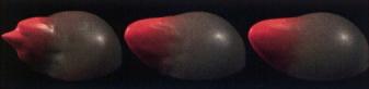
Specular reflection at grazing angles predicted by theoretical models |
|---|
This model does a good job of accounting for the many physical phenomena seen as a result of a rough-surface model, and predicts actual observed phenomena better than older, simpler models. It cannot, however, make any predictions for surfaces that cannot be modeled as having randomly-oriented microfacets. In particular, it cannot model any nonisotropic surfaces. These are surfaces, such as woven cloth or brushed aluminum, for which the BRDF is not independent of azimuth. Therefore, He's model, despite its complexity, is clearly inadequate for predicting all BRDFs that could potentially be of interest in computer graphics.
Instead of extending the purely theoretical models to surfaces of more complex microgeometry, [Westin 92] adopts a simulation-based method of determining the BRDFs of more complex surfaces. Since they are able to start with any desired microgeometry, there is no inherent restriction on the kinds of surfaces their method can model. For example, they have been able to model the reflection characteristics of velvet and brushed aluminum.
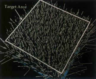
Velvet microgeometry |
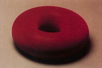
Doughnut rendered using BRDF derived from velvet microgeometry |
|---|
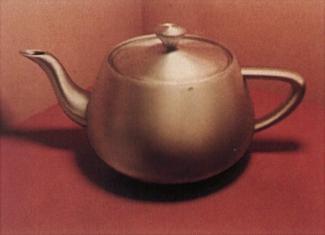
Brushed aluminum teapot using anisotropic BRDF derived using Westin's method |
|---|
The process begins with a scene of arbitrary geometry, representing the microgeometry of a small surface patch. Since the scene is used as input to a ray tracer, the surfaces within the scene can use any known BRDF, and can even be made transparent. The ray tracer follows light incident at random points on the sample as it bounces around the scene, and eventually is scattered back. The algorithm computes, for each incoming angle, the average amount of light reflected into each outgoing angle. Thus, the algorithm approximately determines the BRDF of a surface patch having the given microgeometry.
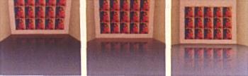
As an alternative to computing a BRDF from some model, one might try to measure the reflectance properties of some sample. The technical challenges involved in doing this are considerable, partly because of the fact that the BRDF is a function of four dimensions. In addition, there are problems with light source and camera stability, with variations in surface geometry, and with interreflection. In fact, one recent survey of BRDF measurement laboratories found huge variations in the results reported for identical samples. [Leonard 93] For this reason, there has been very little work in trying to use measured BRDFs for computer graphics work.
Large variation in measured BRDFs of the same sample |
|---|
One paper that does present a method for acquiring BRDFs is [Ward 92]. Instead of distributing the necessary four degrees of freedom among surface, camera, and light source motion, as is customary in BRDF measurement, Ward built an imaging reflectometer that uses the two degrees of freedom inherent in a camera imaging system to reduce the number of moving parts. The complete system includes a collimated light source, a half-silvered hemispherical mirror, and a fisheye lens. Thus, the system captures the light reflected into all directions at once, since the mirror reflects all the reflected light back to the fisheye lens.
Conventional BRDF measuring apparatus |
Ward's BRDF measuring setup |
|---|
The clever optical setup of Ward's device allowed him to acquire a complete BRDF in only a few minutes, including time to manually rotate the sample. The quality of the data, however, was not very high. This diagram from Ward's paper shows the large amount of noise present in the data he acquired, and the limitations on his field of view. Since Ward fit his data to a model with a small number of free parameters, these were not major problems. They confirm, however, how difficult it is to measure BRDFs, even with careful attention to the measuring apparatus.
Noise and missing data in one slice of Ward's measured BRDF |
|---|
Given the size and high dimensionality of BRDFs, techniques must be developed to store and compute them efficiently. After a brief look at simple techniques, like storing and interpolating raw data samples or evaluating physically-based models on the fly, we will focus on a collection of representations that allow BRDFs to be stored compactly, and computed efficiently when needed. These techniques, to various degrees, make use of the smoothness and symmetry properties of most BRDFs that make them easier to compress than arbitrary four-dimensional functions.
The simplest method of BRDF representation one might envision would be to sample the BRDF on some regular (or irregular) grid, and interpolate among the samples when needed. This is, in fact, a popular method in conventional scatterometry, and data obtained from large BRDF measurement laboratories is likely to be presented in this format. Despite its simplicity, it has a number of drawbacks for use in computer graphics.
First, raw data obtained from measurement is likely to be noisy, as has already been seen [Leonard 93, Ward 92]. This leads to noisy surfaces in the images produced using these BRDFs. Although this is not a problem in domains such as thermal simulation [Arnold 89], it is highly objectionable in computer graphics.
Even if the raw data obtained were perfect, it would still not be suitable for direct use because of missing data. It is impractical to measure the BRDF for angles near grazing angles or, with most apparatus, near the backscatter angle. This means that there will be holes in the data wherever the incident and outgoing directions are very close, as well as near the horizons of both the incoming and outgoing angles. Since grazing-angle BRDFs have a large effect on the human perception of surfaces, it is important to have a carefully smoothed and extrapolated BRDF near the horizon, rather than one extrapolated from raw (noisy) data.
Missing data can also occur because of time constraints in measuring the BRDF. Because of the four degrees of freedom necessary for BRDF measurement, BRDF scans can take a very long time. For this reason, it is common to measure only a relatively small number of 2-D slices through the four-dimensional space [Leonard 93]. As a result, interpolation between these slices is not likely to yield a satisfactory value for the BRDF of intermediate points.
Finally, even if the sampled data were correct and complete (e.g. obtained from a theoretical model or Monte Carlo simulation), the storage of samples is very inefficient because of the size of the BRDF. Storing a complete BRDF sufficiently densely for computer graphics needs is likely to require millions of points, and accessing this data during rendering would significantly slow down a renderer. Again, it is the domain of computer graphics that places specific needs on the denseness at which BRDFs need to be stored. Ian Ashdown has obtained good results in luminaire research by using BRDFs and luminaire photometry data sampled on rather sparse grids [Ashdown 92].
A common tactic in graphics is to fit measured BRDFs to analytic models. These models typically have a very small number of free parameters, and so the fit can cope rather easily with noise and missing data. In addition, since only these best-fit parameters need to be known to reconstruct a BRDF, storage is very efficient. Nevertheless, using these theoretical models is problematic because of computational complexity and the comparative lack of flexibility.
Because of their complexity, theoretical models of BRDFs tend to be inefficient to compute. For example, evaluating He's model requires computing many terms of a slowly-converging series [He 92]. Since during rendering this must be done for a large number of incoming and reflected directions, the evaluation of the BRDF can significantly slow down rendering time.
A more serious drawback to using theoretical models is their lack of flexibility. Each model, to be mathematically feasible, must make certain restrictive assumptions on the class of surfaces it can model. One consequence of this has been the emergence of a large class of ad-hoc empirical models. For example, [Ward 92] presents an "elliptical Gaussian" model that is capable of modeling certain kinds of anisotropy, such as that associated with brushed metals. It is a simple modification to a rough-surface model, with two roughness parameters (in each of two mutually perpendicular directions) instead of one.
Ad-hoc BRDF models have been used for a long time, and each domain has its favorites. One of the first such models was the Minnaert BRDF [Minnaert 41], developed to characterize the reflectance of the moon:
As can be seen, it is a diffuse (Lambertian) BRDF with extra lightening towards the horizons, controlled by the "limb darkening parameter" k. Models like these are often useful, but they cannot be seen as a good general solution in the domain of photorealistic rendering. Aside from issues of physical correctness, these models are applicable for only narrow classes of surfaces. Therefore, human intervention is required to find a model most nearly applicable for a given surface, and even then there is no guarantee that such a model exists.
It is necessary, therefore, to find a framework for representing arbitrary BRDFs, without the waste associated with storing point samples. Four techniques popular in recent years use splines, spherical harmonics, wavelets, and polynomials on a disk, respectively.
One simple extension of interpolating raw data samples is to use spline patches to represent the BRDF. In this way, a much sparser grid can be used, and the resulting BRDF is smoother. In addition, noisy and missing data are not as problematic, since they are handled by the spline fitting algorithm. A further advantage is that the splines are relatively easy to compute. Nevertheless, a spline representation of a complete BRDF can still require a large amount of storage.
[He 92] presents an interesting hybrid representation based on their analytic model, by using a precomputed spline to simplify the computationally difficult parts of the equation. The authors report a large speedup without sacrificing accuracy. In addition, because the spline represents only a small component in the full equation, the storage costs are small.
The major problem with spline representations is that they do not explicitly use the symmetry of most BRDFs. That is, a complex, anisotropic BRDF will probably require about the same storage as a simple, isotropic one. The only way to represent the symmetry is by combining the spline with an analytic model, thus greatly restricting the kinds of BRDFs that are representable. There is no smooth, graceful degradation in the storage costs associated with increasingly complex BRDFs.
A currently very common method of storing BRDFs is by projecting them onto spherical harmonics. These are the spherical analogues of sines and cosines, in that they form a smooth orthonormal basis for functions on the sphere, and are localized in the frequency domain. These properties are useful, since it is easy to project a BRDF onto the basis of spherical harmonics, and since smooth, simple BRDFs will have fewer nonzero (or at least nonnegligible) coefficients than complex ones. The most complete treatment to date of using spherical harmonics to represent BRDFs is [Westin 92].
It turns out that a naive implementation of BRDF representation in terms of spherical harmonics has several problems. First, since the BRDF is defined on the product of two hemispheres, rather than two spheres, there is the question of how to fill in the missing hemispheres of data. Next, truncation of high-frequency coefficients is likely to cause "ringing", because of the sharp edges in frequency space. Finally, even moderately complex BRDFs require large numbers of spherical harmonic basis functions to be represented correctly.
[Westin 92] uses a number of mathematical tricks to overcome some of these limitations. First, the authors choose to fill the "missing" hemispheres with copies of available data, rather than with zeroes. This has the effect of introducing a symmetry into the function, which causes the coefficients of all odd harmonics to be zero. Next, instead of representing just the BRDF, the function they actually store is
This enforces continuity at the "equators" of the spheres, and helps to reduce ringing. They also artificially dampen certain high-frequency coefficients to soften the edges in frequency space, and reduce ringing even further.
A final important feature used to simplify the BRDF representation and increase its physical correctness is the fact that Helmholtz reciprocity is enforced. This principle, arising from the physics of reflection, states that the BRDF must remain the same if the angles of incidence and reflection are interchanged. Therefore, the (four-dimensional) matrix of spherical harmonic coefficients must be symmetric under interchange of incoming and outgoing angles. This not only reduces the storage requirements of the matrix, but also enforces some basic constraints on physical correctness.
The spherical harmonic representation is an attractive one for describing BRDFs, because of the mathematical and conceptual simplicity of the model. Nevertheless, even with Westin's improvements, the number of coefficients required to represent even moderately complex BRDFs is large. Very specular surfaces can be expected to require impractically large numbers of coefficients to represent the sharp reflective peaks accurately.
One may summarize the problems with the spherical harmonic representation by pointing out that though the basis functions are well-localized in the frequency domain, they are not at all localized in the spatial domain. Therefore, sharp features in the BRDFs will cause ringing in other areas unless a large number of coefficients is used. On the other hand, representations that are localized in space, such as splines, require many coefficients even when the surfaces are smooth. Therefore, what is really necessary are functions localized in both the spatial and frequency domains. The research conducted into wavelets has shown that it is possible to find such functions, group them into orthonormal bases, and develop efficient algorithms for computing them.
The particular implementation of wavelets we will consider is that of the "second-generation" wavelets of Sweldens and Schröder. By using what they refer to as a lifting scheme, they are able to construct wavelets on nearly arbitrary domains, without the mathematical difficulty and other limitations associated with classical "first-generation" wavelets. The resulting wavelets have compact support, smoothness (decay towards high frequencies), and vanishing moments (decay towards low frequencies). Wavelet coefficients can be computed efficiently by means of a "fast wavelet transform".
[Schröder 95] describes a basis of second-generation wavelets adapted for representing functions on a sphere. The functions are stored on a subdivided icosahedron, and several classes of wavelets suitable for that basis were found. The authors report good results in storing BRDFs using these bases, even using relatively small numbers of coefficients. They also point out that this representation is particularly well-suited for hierarchical illumination algorithms, and multiresolution analysis.
Successive subdivisions of icosahedron |
|---|
According to the paper, the main cost associated with computing the wavelet representation is determining the optimum set of coefficients to keep. Since this must be done once per BRDF, however, this is not a major drawback. The computation required to compute the BRDF for one particular pair of incoming and outgoing angles, which is the computation performed in most conventional renderers, is proportional to the depth to which the tree of coefficients must be expanded, which is approximately logarithmic in the number of coefficients. This compares favorably with the spherical harmonic representation, which requires computation time proportional to the number of coefficients.
Wavelet representations of one piece of a BRDF Images use 19, 73, and 203 nonzero coefficients, respectively |
|---|
The preceding two approaches have been sphere-based, in that they look at functions on a hemisphere as a special case of functions on a sphere. An alternative approach is to map the points on a hemisphere onto a disk. One recent paper explores this possibility, looking at representing BRDFs in terms of an orthonormal basis of functions on the unit disk.
[Koenderink 96] starts with the Zernike polynomials, commonly used in physical optics. These functions are then projected onto a hemisphere using an equal-area mapping. The "cross-product" of these sets of functions is now suitable for representing functions defined on a pair of hemispheres. The authors the observe that the set of representable functions can be restricted to those satisfying reciprocity by forming a new basis from particular linear combinations of the original basis functions. Thus, the paper develops a representation very similar to that used in [Westin 92], but optimized for the hemisphere rather than the sphere.
Unfortunately, the hemispherical basis shares many of the faults of the spherical harmonic basis. The basis functions are not spatially localized, and representations in terms of the basis are susceptible to ringing. In addition, evaluating the BRDF at a particular incoming and outgoing angle requires computation time proportional to the number of nonzero coefficients. Therefore, the storage and computation costs of using the Zernike-based representation are likely to be considerable. Creating a basis specialized to the hemisphere, though, is a good idea, and might be applicable to other methods, such as wavelets.
We will now look at some areas for possible future research in BRDF representation. In general, there is a need both for more efficient and computationally inexpensive BRDF representations, and for extended (especially spatially-varying) BRDFs.
It is interesting to note that the most popular surface reflectance model currently in use is the Phong model. The reason for this is simplicity - the Phong model gives results that are often "good enough", and it can be computed extremely quickly. This shows that BRDF representations can succeed even if they are not extremely accurate, provided BRDF computations do not significantly slow down the renderer. The problem with current BRDF representations is that they introduce visible and objectionable artifacts (e.g. the ringing associated with spherical harmonics) when the BRDFs are compressed too much. Therefore, it would be useful to find methods that are free of such visually jarring artifacts, even when relatively few coefficients are kept.
One approach to improving BRDF representation is to use more of the symmetries present in most natural BRDFs. The most obvious example here is Helmholtz reciprocity - it would be interesting to add this constraint to the spherical wavelet representation. A second, potentially more useful, symmetry arises from the fact that most BRDFs are very similar when looked at from the direction of natural reflection. That is, if for a given incident direction we look at the pattern of reflected light centered around the direction of the mirror reflection of the incident ray, this pattern (ignoring the effects of the horizon) will vary slowly with the direction of the incoming ray. Therefore, if we perform a change of basis before we represent the BRDF we should see slow variation along one axis, potentially leading to better compression. The challange of dealing with the "moving" horizon in this new basis, however, might make implementing such a change of basis impractical.
A second idea for improving BRDF storage is to use a combination of one of the flexible methods (such as the wavelet representation) and a simple analytic model. For example, we could perform a best fit of the data to Ward's Gaussian model, and represent the residual using the wavelet basis. This should provide much better performance, especially in quickly-varying BRDFs. In fact, this is possibly the only solution for representing BRDFs with sharp specular peaks without using large numbers of coefficients.
A final idea for improving BRDF representation deals with color. Most papers on representation pay little attention to color, assuming that whatever representation is chosen can simply be repeated three times for the red, green, and blue components. It might make more sense, though, to use an HSV basis to represent color. For many BRDFs, the variation in one or more of these components will be minimal. For example, many plastics will exhibit variation only in saturation and value, while metals will vary only in value, except near grazing. Switching to an HSV basis should require little change in the representation algorithms, except perhaps to deal with the wrap-around of the hue component.
True photorealistic rendering will require that we re-introduce some of the dimensions we dropped from the BRDF. For example, to obtain physically accurate results when there are multiple reflections in a scene, we need a better model of color, and some provisions for polarization. Color should be fairly easy to improve, either by sampling the visible spectrum or by using some basis functions. Polarization, however, is more difficult, since in the general case we need to account for linear, circular, elliptical, or random polarization, or combinations of all of these. A simple start might be to represent the BRDFs for linearly polarized incident rays only, storing the values for polarization parallel and perpendicular to the plane of incidence. This will allow for the modeling of the most important polarization-related effect, namely the total linear polarization of light reflected at Brewster's angle from a dielectric.
The most important dimensions to be added, though, are the spatial ones. BRDFs naturally vary with position on a surface, and it is important to model this variation. The problem is, of course, that adding these two additional dimensions will greatly increase the size of the data set. Although it should be possible to represent entire six-dimensional spatially-varying BRDFs directly, it is probably much more practical to use some approximate methods. For example, one can conceive of a surface representation that has a small set of basis BRDFs, and a sampled or procedurally generated "texture mask" that modulates between them. This would be a natural extension of conventional texture maps and bumpmaps, and should be capable of accurately reproducing a large class of real-world materials.
It might also be interesting to incorporate BRDFs into texture synthesis
algorithms, such as those presented in [Heeger 95] and [Lewis 89]. One
motivating example of a situation where this might be useful is the speckle
associated with materials such as sandstone. The BRDF in this situation has
sharp specular peaks that vary randomly in orientation throughout the surface.
Other examples include coarsely-brushed finishes on metals, or cloth.
Many representations for BRDFs have been proposed in the computer graphics
literature. Of those considered here, the one based on wavelets seems to be
the most space efficient and quickest to compute. More work is needed to make
the method more stable and free of artifacts, possibly by making use of more
symmetries and constraints. The most important area for future research,
however, is in efficiently extending BRDF representation to accomodate spatial
variation.
| [Arnold 89] | Arnold, C. B. and Beard, J. L. "An ERIM perspective on BRDF measurement technology", SPIE Vol. 1165 Scatter from Optical Components, 1989. |
| [Ashdown 92] | Ashdown, I. "Near-Field Photometry: A New Approach", 1992. |
| [He 91] | He, X., Torrance, K., Sillon, F., and Greenberg, D. "A Comprehensive Physical Model for Light Reflection", Siggraph 1991. |
| [He 92] | He, X., Heynen, P., Phillips, R., Torrance, K., Salesin, D., and Greenberg, D. "A Fast and Accurate Light Reflection Model", Siggraph 1992. |
| [Heeger 95] | Heeger, D. and Bergen, J. "Pyramid-Based Texture Analysis/Synthesis", Siggraph 1995. |
| [Koenderink 96] | Koenderink, J. J., van Doorn, A. J., and Stavridi, M. "Bidirectional Reflection Distribution Function Expressed in terms of surface scattering modes", ECCV 1996. |
| [Leonard 93] | Leonard, T. A. and Rudolph, P. "BRDF Round Robin Test of ASTM E1392", SPIE Vol. 1995 Optical Scattering, 1993. |
| [Lewis 89] | Lewis, J. P. "Algorithms for Solid Noise Synthesis", Siggraph 1989. |
| [Minnaert 41] | Minnaert, M. "The Reciprocity Principle in Lunar Photometry", Astrophysical Journal, Vol. 93, 1941. |
| [Schröder 95] | Schröder, P. and Sweldens, W. "Spherical Wavelets: Efficiently Representing Functions on the Sphere", Siggraph 1995. |
| [Ward 92] | Ward, G. "Measuring and Modeling Anisotropic Reflection", Siggraph 1992. |
| [Westin 92] | Westin, S., Arvo, J., and Torrance, K. "Predicting Reflectance Functions from Complex Surfaces", Siggraph 1992. |