Random Noise - see the middle image in the bilateral smoothing example, below.
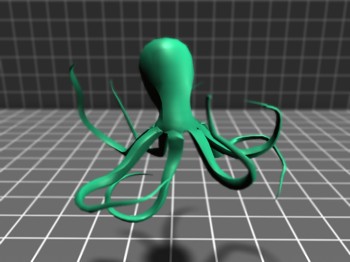
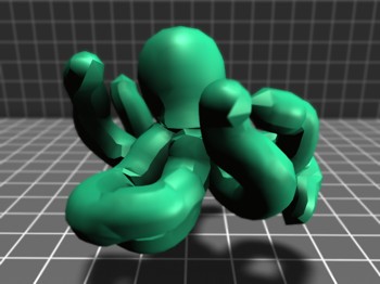
Inflate - This octopus model has been inflated by 3 units to produce the model on the left
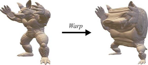
Fun - In this example, the center of the model is made larger, while the outside is shrunk, all while keeping the model inside the original bounding box. This leads to the warping effect seen here. This example is taken from the paper "Real-time Mesh Simplification Using the GPU", which contains the details of the warp function.
Warping with Point Correspondences - Example coming soon...
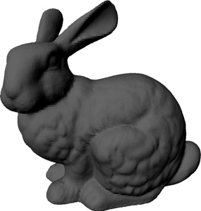
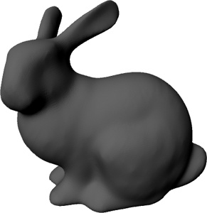
Smooth - By setting each vertex to the gaussian-weighted average of its neighbors, we can smooth a model. In the example, the original bunny on the left has been smoothed - many times - to produce the example on the right.
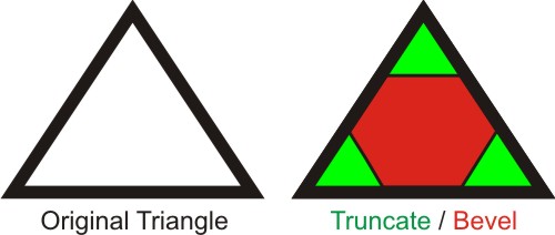
Truncate / Bevel - We show an example in 2D for clarity. For the given triangles, we create new vertices 1/3 of the way along each edge. For the truncate operation, we take the green portion; bevel takes the red portion.
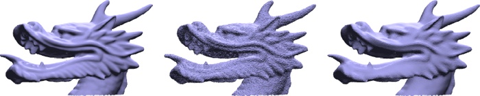
Bilateral Smoothing - The best example is the teaser from the paper "Non-iterative, Feature-Preserving Mesh Smoothing", which is shown below. Noise has been added to the dragon on the left, producing the middle, which is smoothed to reproduce the right. As with the bilateral image filter, this will smooth noise while preserving model detail edges.
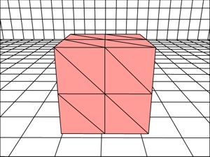
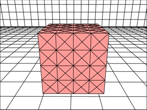
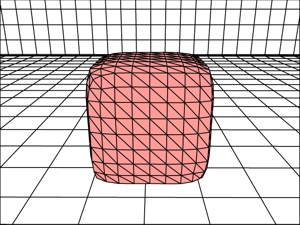
Subdivide Faces / Split Long Edges - Both will add additional faces to the model. Note that you should probably do this by creating a new mesh to store the additional faces, as managing which ones have been deleted and added is likely to be a hassle (and remember, small constant efficiencies aren't important!). Given the original on the left, splitting the edges will increase the tesselation, while keeping the overall shape the same. By contrast, Loop subdivision will start smoothing the corners of the object.
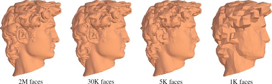
Vertex Clustering - By dividing the bounding box of the mesh into a cubic grid, and collapsing all vertices inside each grid cell to a single vertex, while keeping the triangle connectivity, we can reduce the resolution of a mesh. The grid sizes below are about 50x50x50, 25x25x25, and 15x15x15. To compute the single, "representative" vertex for each cluster, you can just use the average in that cell. The image is taken from "Real-time Mesh Simplification Using the GPU"
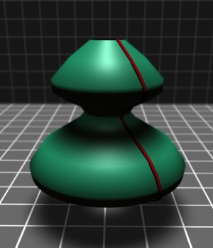
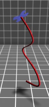
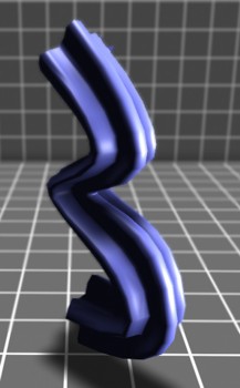
Surface of Revolution / Surface Sweep - The red line below is revolved around the vertical axis, producing the green figure. In the second figure, we show the same profile curve, which is used with the blue polygon to produce the sweep-surface in the right figure.
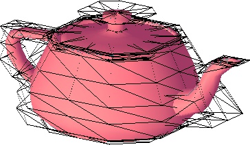
Bezier Patch - You can download teapot_bezier.txt for the corresponding data file. The data consists of a number of patches; each patch is 16 control vertices sequentially; each vertex is x,y,z coordinates. I would strongly suggest you make sure you can load the vertices correctly first before attempting to create a patch. One way is to simply make triangles connecting adjacent vertices. Note that the black polygons in the example represent the control vertices of the patches. Click here for an interactive demo.
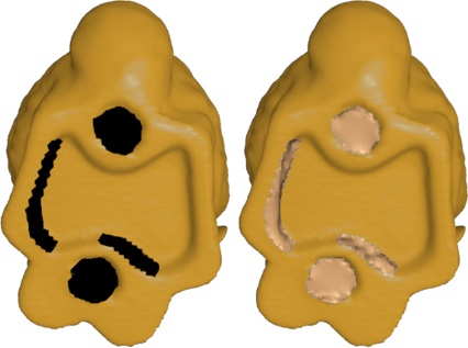
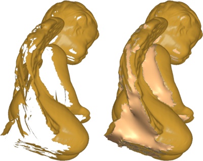
Fill holes - The base of the bunny model (left) and this angel (right) are aquired from scanned data sources, which produces holes in regions invisible to either the camera or laser, requiring hole-filling operations.
 |
 |
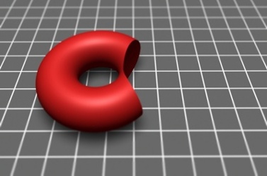 |
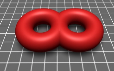
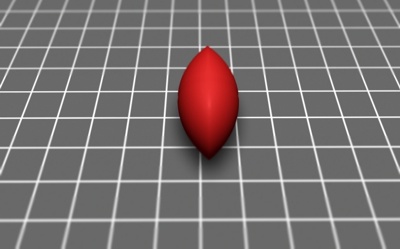
| Union | Intersection | Difference |