Laboratory #2: Sensors, Resistance is not Futile!!
Care and Feeding of Interface Boards and Sensors
Please be cautious with wiring, and especially connecting batteries. Connecting a battery backward, only for a
moment, can fry many components. Be careful with the wires connected to the sensors,
as they can break off.
What to touch (and not)
Nothing in this lab can hurt you, unless you're
allergic to something nobody else in the world is. Don't, however, touch
any bare
wires when running experimental trials (it's ok to touch them when
setting up things of course). Hold the devices by the insulation on
the wires, not on the soldered connections (if exposed). You'll see
why in section 4 below.
The Parallax Basic Stamp II
For some of the hardware labs, we'll be using the Basic Stamp II from Parallax Inc.
It's pretty cool for doing quick interface circuits, but
sort of dumb from a programming perspective. It's also sort
of slow compared to some processors (but so are almost all human motions).
Directories, files
You might want to make your own directory, either
in your home directory as mounted and mapped
from the CS or Princeton domain, or just make
one on the desktop and name the folder with your name or group.
Note that putting a directory on one desktop won't make it appear
on any other machine in the lab, nor outside the lab. This is sort of a drag, but it's Windows.
1. Force Sensing Resistors
1.1 Measuring Position Using an FSR
First, we will use a
Linear Force Sensing
Resistor to measure position.
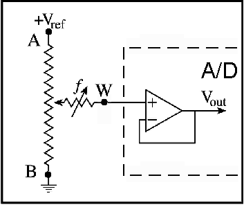
The circuit shown in Figure 1-1 will be used to
measure the output of the FSR.
 |
| Figure 1-1: Linear FSR Measurement Circuit |
Procedure:
- Connect the interface board to a PC using the serial port/cable.
- Connect the black wire from the long FSR to the black terminal on the
interface board.
- Connect the red wire coming from the long FSR to the red terminal.
- Connect the remaining wire from the long FSR to the terminal marked A0
(it's channel 0 of the A/D converter).
- Load this Basic Stamp code
It should launch the
BasicStamp
editor/loader/debugger program, but
if it doesn't
you can cut and paste it into a Stamp editor
(get it above or from parallaxinc) window.
- Connect a 9 volt battery to the interface board
- Select "Run", "Run" from the Stamp Editor Menu
Depending on your platform and version of the Stamp Editor/Loader,
the editor might complain and offer to fix various things.
Basically let it do what it wants and things usually work out.
If all has worked well, a debug window should appear and
numbers should begin scrolling down, in that window.
If not, check
battery, wiring, serial port selection, etc.
Questions:
- What happens as you press on the FSR in various locations ?
- Is the output a function of where you press it? How?
- Is the output a function of how hard you press?
(Note: try to keep the surface area constant.
For example, you could use a pencil eraser to touch the Linear
Position FSR. Do not use anything sharp!) How?
- What happens when you don't press it at all? Comment on this.
- What is the numerical range of the sensor?
- How fast can you tap the sensor and see the effects?
- What kind of signal conditioning circuit is Figure 1.1?
- What are the pros and cons of using this circuit?
1.2 Measuring Force Using an FSR
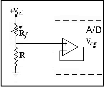
Here we'll use the circuit shown in Figure 1-2:
 |
| Figure 1-2: Pressure FSR Measurement Circuit |
Procedure:
- Remove the long FSR from the terminals of the interface board.
- Connect the black wire of the square FSR to the black terminal on the interface board.
- Connect the red wire to the red terminal.
- Connect the remaining wire to the A0 terminal.
- Use the same program for the Basic Stamp as you used above
Questions:
- Is the output a function of how hard you press?
- Is it different from the Linear FSR in section 1.1?
- What is the numerical range of the sensor circuit?
- How fast can you tap the sensor and see the effects?
Procedure:
- Lay the square FSR on the table, and lay one quarter coin on it.
Record the numeric output in response to this weight.
- Lay another quarter on top of it (2 total). Record the numeric
output.
- Lay a third quarter (3 total). Record the output.
- Repeat this for 4, 5, and 6 total quarters.
Questions:
- Plot the responses as a function of the number of quarters.
- Was the output a linear function of the number of quarters?
Procedure:
- Load and run this new Basic Stamp program.
- Click the "Clear" button on the Basic Stamp Debugger window.
- Have one lab partner depress and hold the "reset" button on the interface board.
- Have another partner (you maybe) get ready to depress the FSR with your finger.
- Have the "reset-partner"
start the data collection by releasing the reset the button, while you
immediately but slowly increase the pressure on the sensor. Try to linearly
increase pressure across the data collection time, but DO NOT look at the
data while doing it! Be sure to have one lab partner say
"go" and release the reset button while another pushes the FSR. You might need to do this a couple of times before you get a good trial of you increasing the pressure on the FSR over the whole time the stamp collects the values.
- You'll note that the debug window prints a string of numbers, then stops. Select
all the text in the debug window (note that you should have cleared any prior text
by clicking the "Clear" button. If you didn't, then repeat the last 4 steps).
Copy it using CONTROL-C (You will receive absolutely
no confirmation except that the text will become de-selected, but ctrl-c should
capture any selected text. Future versions of the
Parallax debugger promise file capture, but for now we have to do it manually).
- Open WordPad and paste the captured debug text into it.
- Save the file as ascii text, in a file called fsrBLAB.txt (where BLAB is some name related to your group). Save it somewhere convenient like root level on the c: drive
(it's just a temp file, and we want to get to it easily using command line
functions such as "cd"). Put in something meaningful for BLAB so you won't get your data confused with some other group.
- Launch MATLAB
- cd to the directory where you saved your fsrBLAB.txt file. like: "cd c:\"
you can type "dir" or "ls" to see if your fsrBLAB.txt file is there.
- type fsrdata = load('fsrBLAB.txt');
- type plot(fsrdata);
If all worked right, you'll be looking at a plot that was captured from your FSR pressing experiment.
If not, check and repeat all prior instructions carefully.
Questions:
- What is the relationship between pressure on the sensor and the numeric
output of the circuit?
- Devise a MATLAB function to linearize the relationship between pressure
on the sensor and the plotted result.
Procedure:
- Go back and acquire another buffer of samples while simply holding the
square FSR sensor in your hand, but applying no pressure.
- Save the data in another file (handfsr), load it, and plot it in MATLAB using:
>> plot(handfsr,'red')
- type in the MATLAB prompt:
>> hold on
- Go back and acquire another buffer of samples with the sensor at rest on
the table.
- Save it in another file, (tablefsr), load it, and plot the result in MATLAB using:
>> plot(tablefsr,'green')
You'll note that both plots are now superimposed. This was caused by the "hold on"
command. You can type "hold off" to cause the plot to clear next time a plot is made.
Questions:
- What do you see in the two plots?
- Are they different? Why might this be?
2. Potientiometers
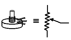
Here we'll measure the rotational position of a rotary potentiometer
shown in Figure 2-1.
 |
| Figure 2-1: Drawing and electronic symbol of a potentiometer. |
Procedure:
- Disconnnect any prior-connected FSRs from the interface terminals.
- Connect the potentiometer, wiring as before, black to black, red to red, other to A0.
- Load and run the original
continuous display A/D program
- What is the numerical range of the output?
- What is the approximate degree rotation range of the potentiometer?
- What is the approximate resolution of the sensing system (in integer values per degree)?
- Based on the maximum numeric output of the A/D, how many bits are required
to store this value? Assuming perfect linearity of the A/D, if Vref = 5 volts,
how many volts per unit difference in the output are represented by the A/D?
Here we'll look at a linear potentiometer, as shown
in the same Figure 2-1.
Procedure:
- Disconnnect any prior-connected devices from the interface terminals.
- Connect a linear (slider) potentiometer, wiring as before, black to
black, red to red, other to A0.
- Load and run the original
continuous display A/D program
- What is the numerical range of the output?
- Is is linear in position (do the positions 0.0, 0.1, 0.2, ... 0.9.
1.0 reflect similar integer outputs in the A/D readings)?
- If not, how might you explain the output, and how might you propose to
linearize the output if required for your application?
3. Bend-sensitive Resistor
Procedure:
- Disconnnect any prior-connected FSRs/Pots from the interface terminals.
- Connect the bending FSR, wiring as before, black to black, red to red, other to A0.
- Load and run the original
continuous display A/D program
- Bend the flexible resistor both ways, try some different shapes (note:
do not kink the resistor in a sharp corner, or you might permanently
damage the device).
- What is the numerical range of the output?
- Is the output symmetric for bending one way vs. the other? Why might
this be?
4. Oh My!! I'm resisting!
Procedure:
- Disconnnect any prior-connected FSRs/Pots from the interface terminals.
- Connect the bare wire harness, wiring as before, black to black, red to red, other to A0.
- Hold the wires by the insulation on the table, and press your thumb and index finger of one hand gently onto the bare ends. Observe and note the output values.
- Now press harder, then as hard as you comfortably can. Observe and note the output values.
- Now lick (or dip in water) your thumb and index finger (I know it's gross, but this is science), and press down hard on the bare wires. Observe and note the output values.
- What did you observe for your finger trials??
- Can you think of an HCI use for skin resistance? What?
- What would be some disadvantages of using skin resistance for a general HCI interface?
5. Photo-sensitive Resistor
Procedure:
- Disconnnect any prior-connected FSRs/Pots/Humans from the interface terminals.
- Connect the photoresistor, wiring as before, black to black, red to red, other to A0.
- Load and run the original
continuous display A/D program
- Cover the photoresistor entirely with your hand.
Don't touch any bare wires. Observe the output.
- Aim the photoresistor directly at light. Don't touch any bare
wires. Observe the output.
- Wave your hand, fingers, etc. over the device. Observe the effect.
- Place the photoresistor on the table, pointed at the light source in the room.
Move about the room some and see if it affects the output.
- What is the total numerical range of the output?
- Describe the behavior of the photoresistor in the above experiments.
- Disconnect the battery from the interface board.
THIS IS VERY IMPORTANT,
as dead batteries are frustrating to all.
(The next lab group could be you.)
- Disconnect any devices connected to the terminals. Put all sensors carefully
back in the box in the lab.
-
General question: Based on the total range of the A/D for all
sensors (largest and smallest numbers you saw), how many bits
resolution is it?
-
Practical HCI system thought problem: Range of motion in human joints is a
very important metric for diagonisis and treatment of many conditions,
and for the study of sports, dance, and other body-related activities..
Given what you've learned about the devices in this lab, describe and sketch
a system for measuring the bending range of a human elbow or knee.
CS436:
Human-Computer Interface Technology, Princeton University, Autumn 2005
Authors: Perry Cook
Copyright © 2002-2005, Princeton
University


