
rotate( mesh, rotate )Rotates a mesh ( or a selected part ) around selected axis, by number specified in the sliders. Unit used for rotation is radian.
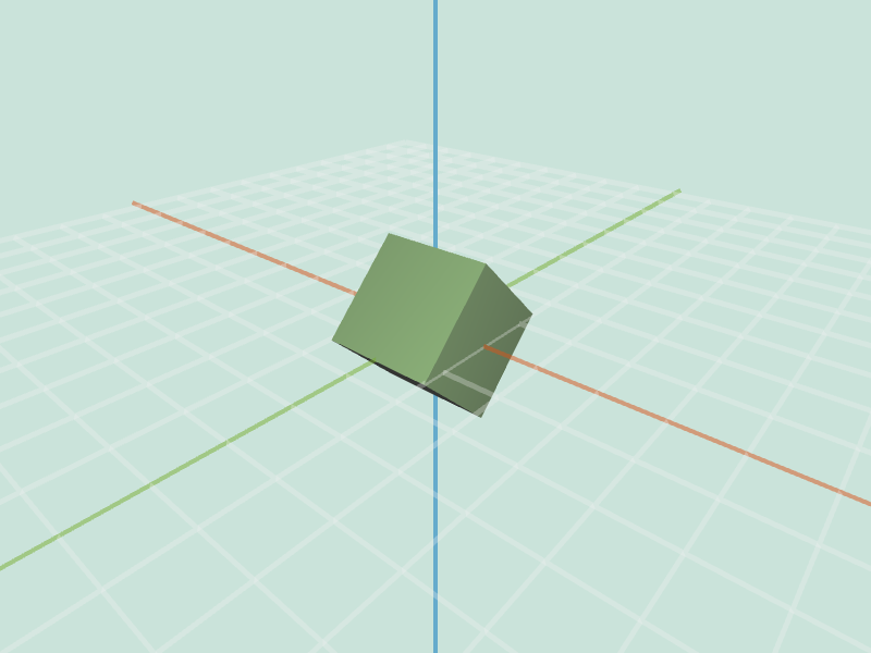 cube.obj rotateX -0.8 |
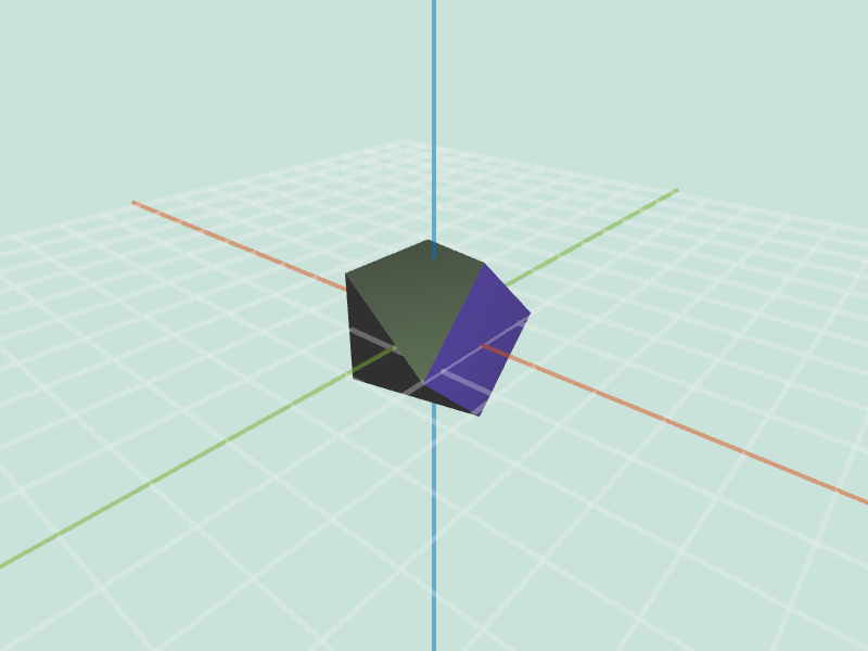 cube.obj (selection) rotateX -0.8 |
twist( mesh, factor )All vertices v are rotated along the Y axis by v.position.y * factor. Units are again radians.
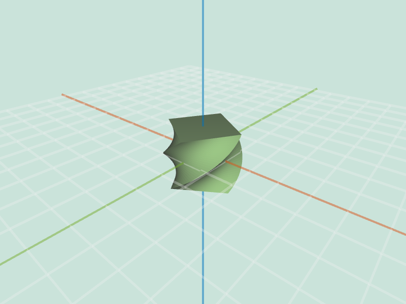 large_cube.obj twist 1 |
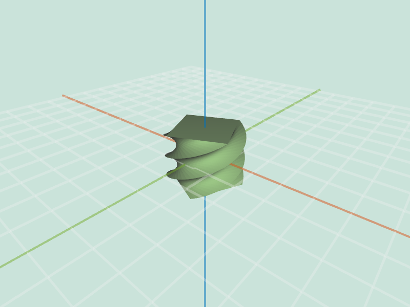 large_cube.obj twist 2 |
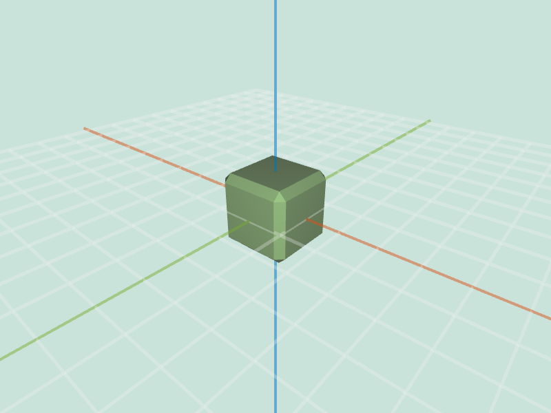
inflate( mesh, factor )All vertices are moved along the direction of respective vertex normals, proportional to factor. For a cube.obj this operation will give scaling effect.
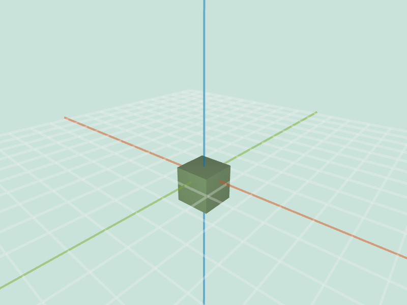 cube.obj inflate -1 |
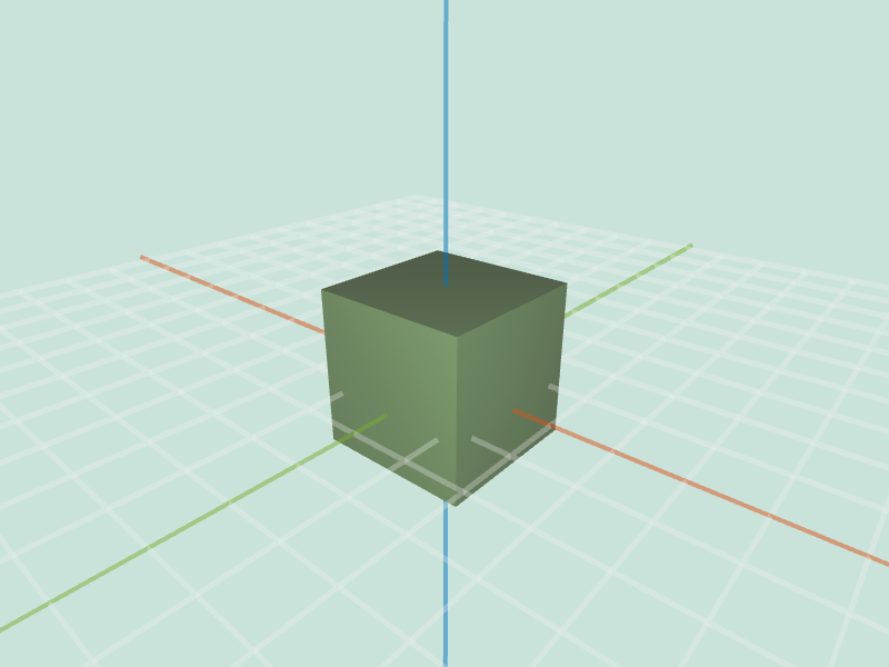 cube.obj inflate 1 |
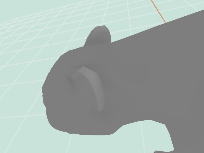
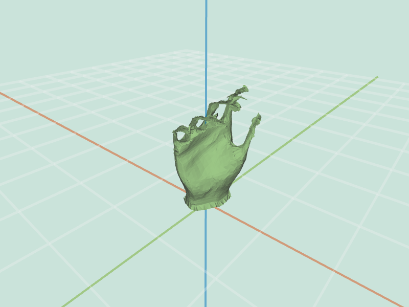 hand.obj inflate -0.1 |
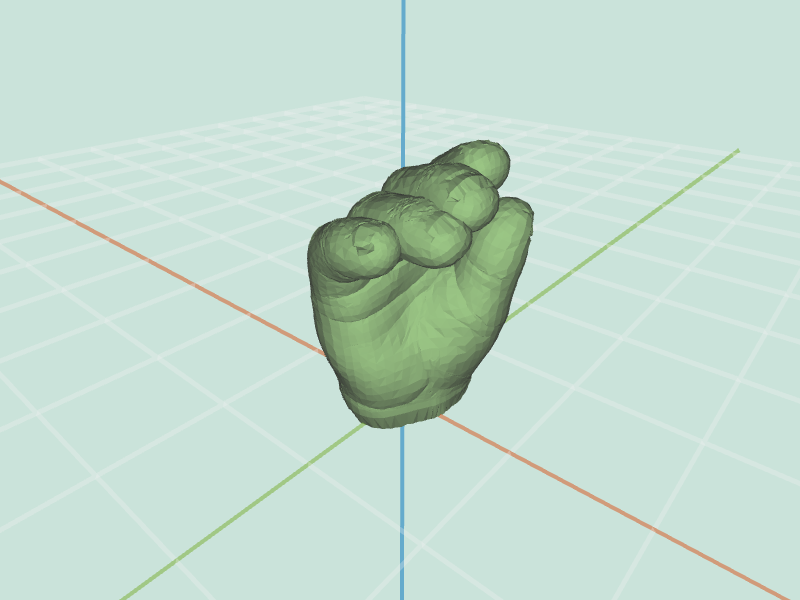 hand.obj inflate 0.1 |
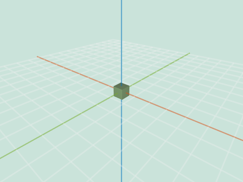 cube.obj inflate -1 |
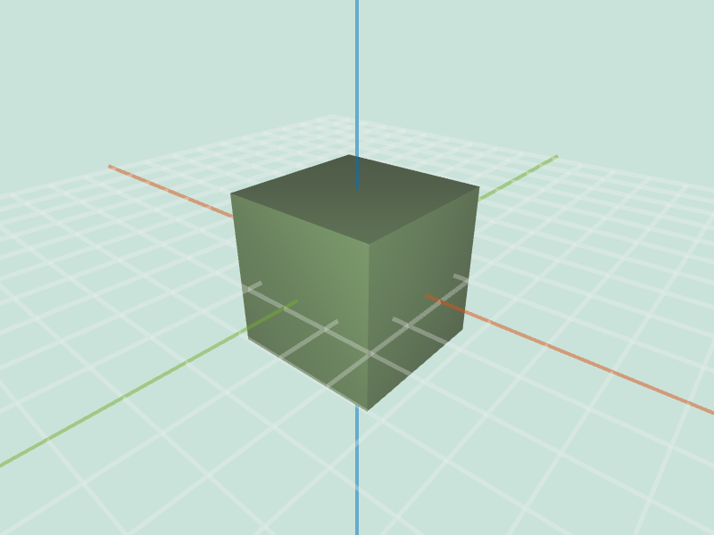 cube.obj inflate 1 |
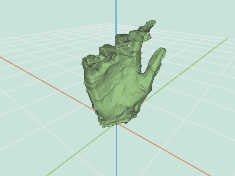 hand.obj inflate -1 |
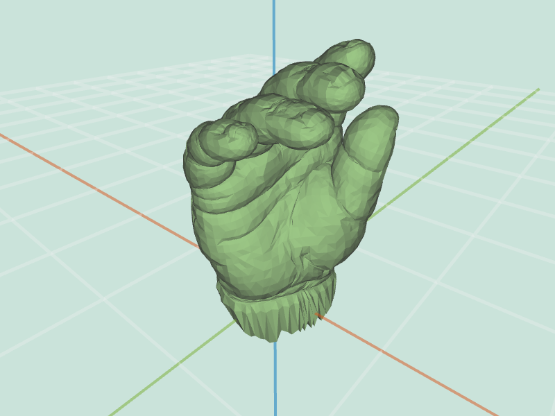 hand.obj inflate 1 |
twist( mesh, factor )All vertices are moved along the direction of respective vertex normals, proportional to mesh.averageEdgeLength(v) * factor * randomIn( -1, 1 ).
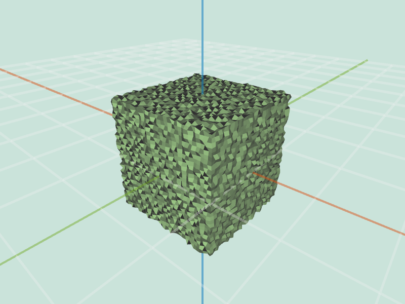 large_cube.obj noise 0.5 |
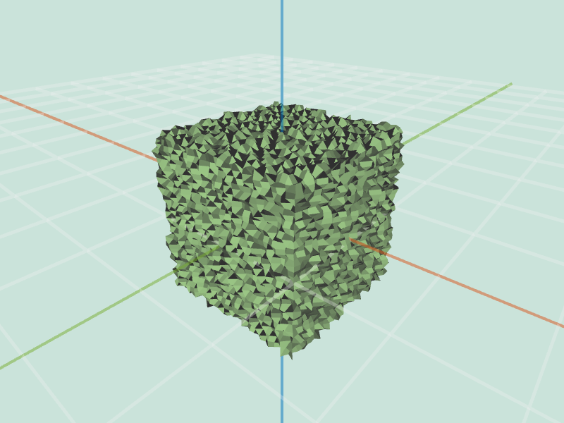 large_cube.obj noise 1 |
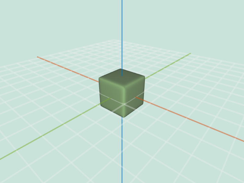
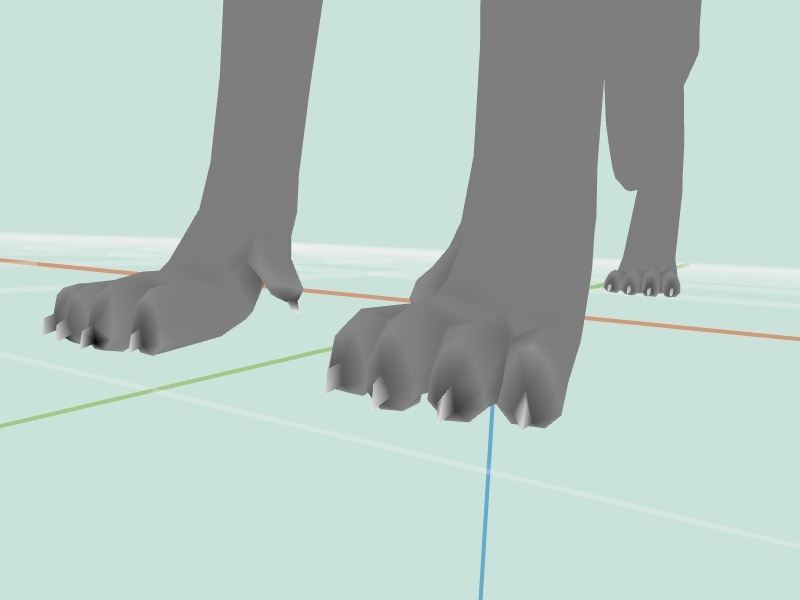
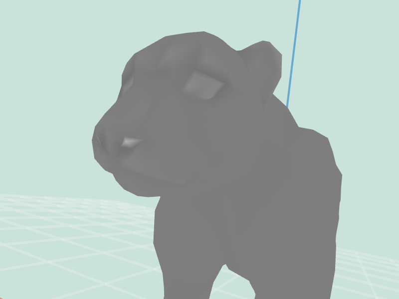
smooth( mesh, iter )This operation needs to be applied iter number of times. Each iteration vertices should be moved to the weighted average of its neighbors. Be careful when updating the position as during single iteration you want to use original positions throughout the entire computation. Update the actual positions of the vertices only after all new locations have been calculated.
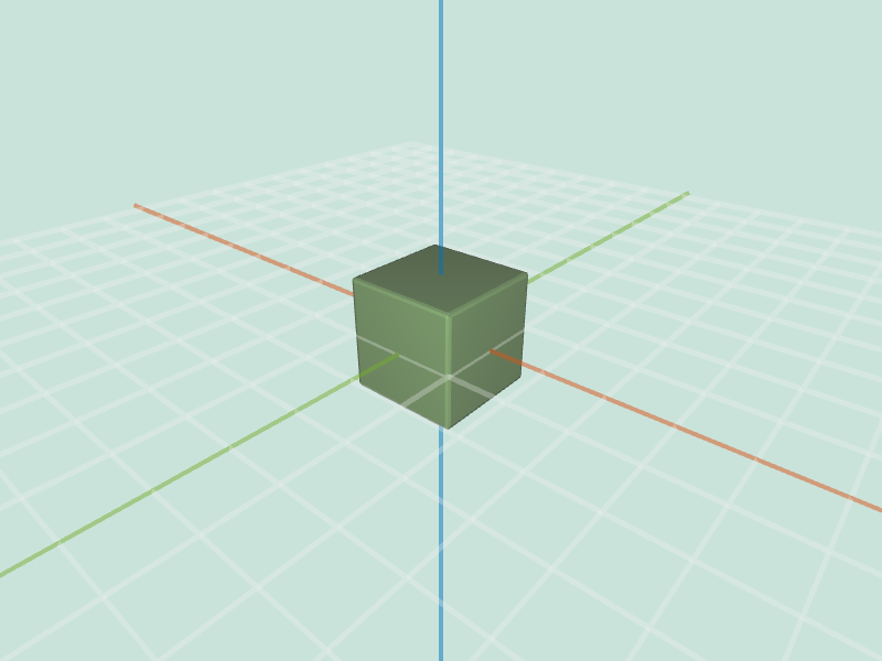 large_cube.obj smooth 1 |
 cube.obj smooth 10 |
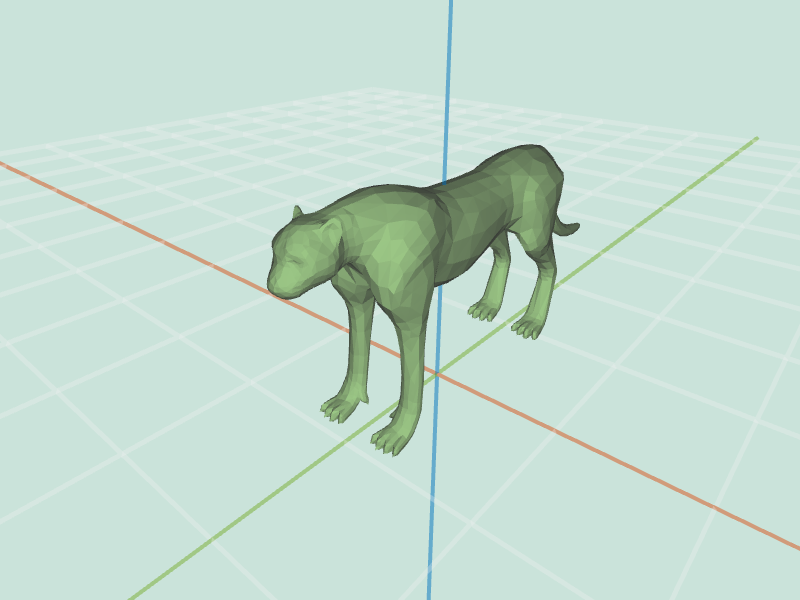 cheetah.obj smooth 1 |
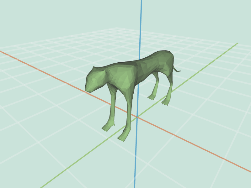 cheetah.obj smooth 10 |
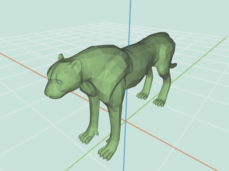
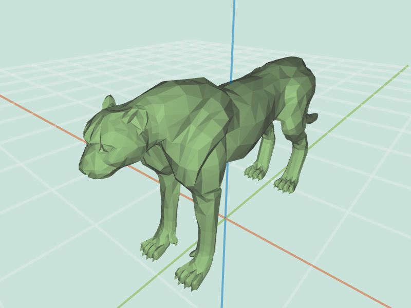
sharpen( mesh, iter )This operation needs to be applied iter number of times, similarly to smooth. If you having display issues consider checking triangulate. ( Assumes you have implemented triangulate filter )
 cheetah.obj sharpen 0 |
 cheetah.obj sharpen 1 |
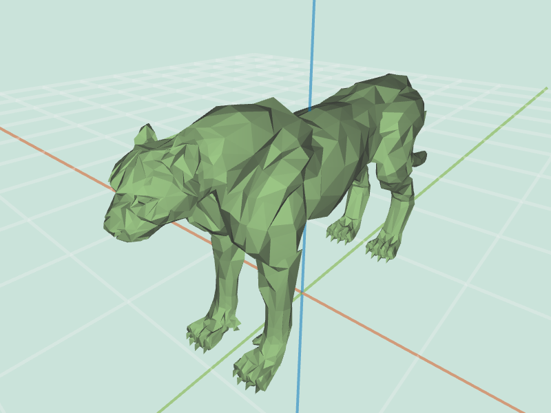 cheetah.obj sharpen 2 |
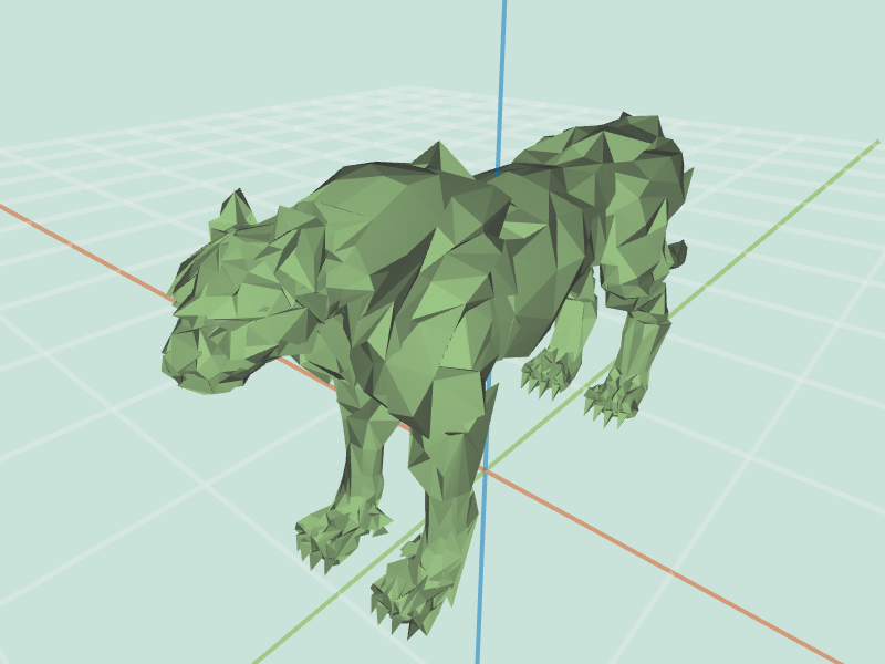 cheetah.obj sharpen 3 |
curvature( mesh )Depending on your choice of visualization, your results might greatly vary from this. However, for cheetah, what you should be seeing is high ( white in our visualization ) values in places like claws, nostrils or ears, and low ( black in our visualization ) around the claws. This due to the fact that Gaussian curvature is defined as product of principal curvatures.
 cheetah.obj curvature |
 cheetah.obj curvature |
 cheetah.obj curvature |
truncate( mesh, factor )This effect should create effect where each vertex is "cut off". It is possible to accomplish that using the splitEdge() and splitFace() functions. Topologically we are only adding vertices, so there is no need to remove any vertices. Think about necessary topological and geometrical changes.
 cube.obj truncate 0.2 |
 cube.obj truncate 0.4 |
 cube.obj (selected) truncate 0.4 |
extrude( mesh, factor )Vertices of each face should be duplicated and moved along the normal of the face. Original face should be attached to duplicated vertices. Set of original vertices and duplicated vertices should be connected together by new faces. This feature requires you to modify half edge data structure by using addVertex( position ), addFace(), and addHalfedge( v1, v2, f ) functions. Make sure you familiarize yourself with those!
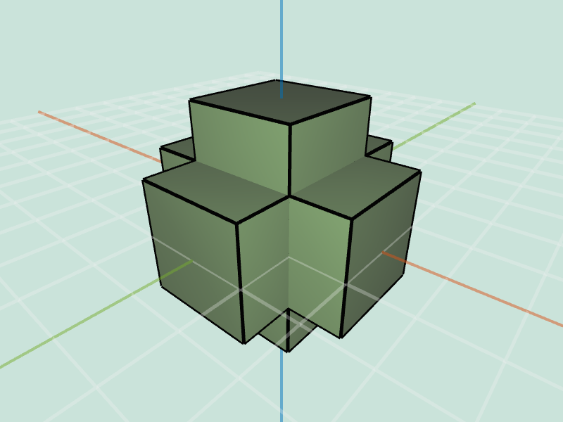 cube.obj extrude 1 |
 cube.obj (selected) extrude 1 |
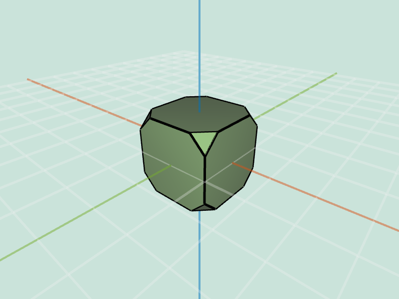
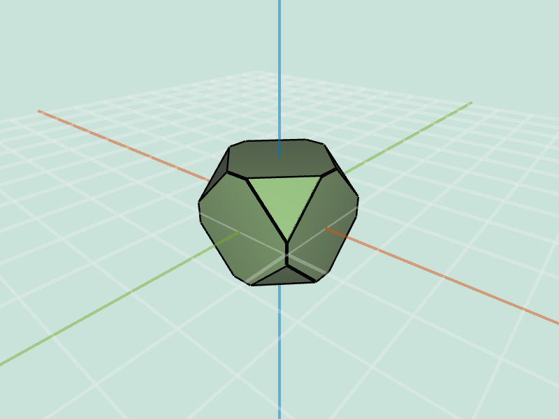
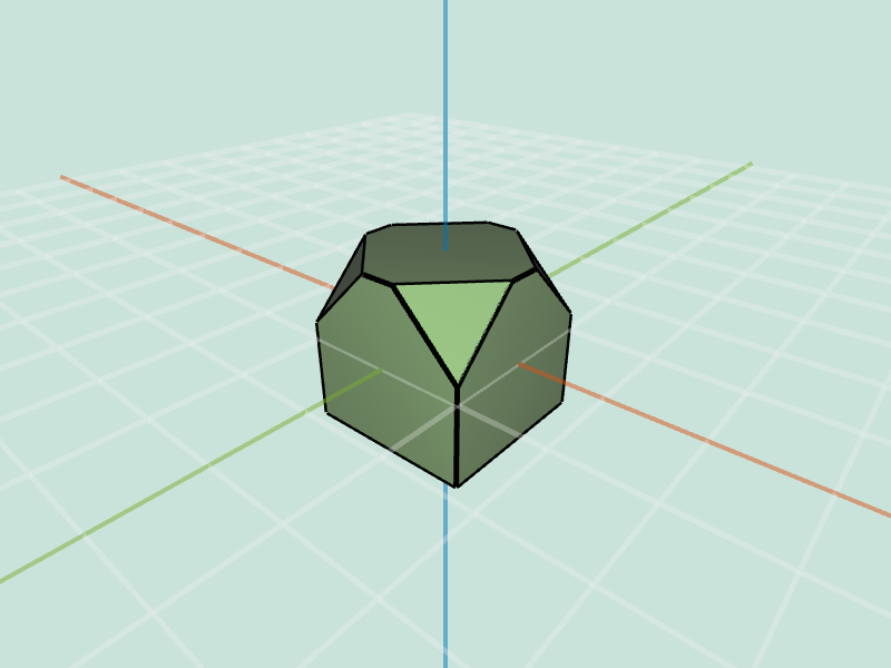
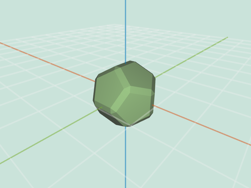
bevel( mesh, factor )This effect should create effect where each edge is "cut off". Please refer to the precept 5 slides for some tips on implementing this feature.
 cube.obj bevel 0.2 |
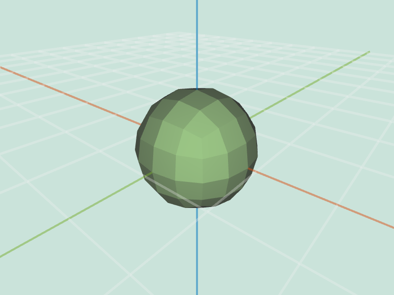
 dodacahedron.obj bevel 0.2 |
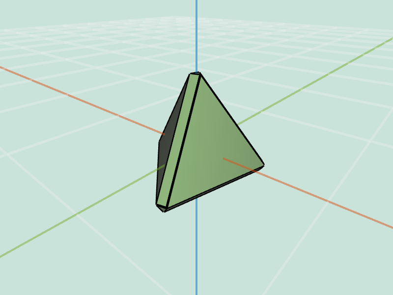 tetrahedron.obj bevel 0.2 |
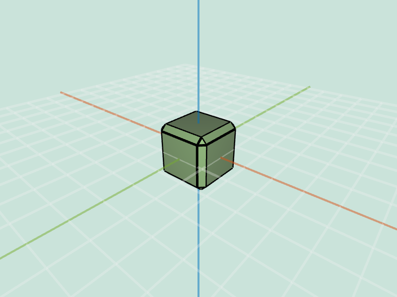 cube.obj bevel 0.2 |
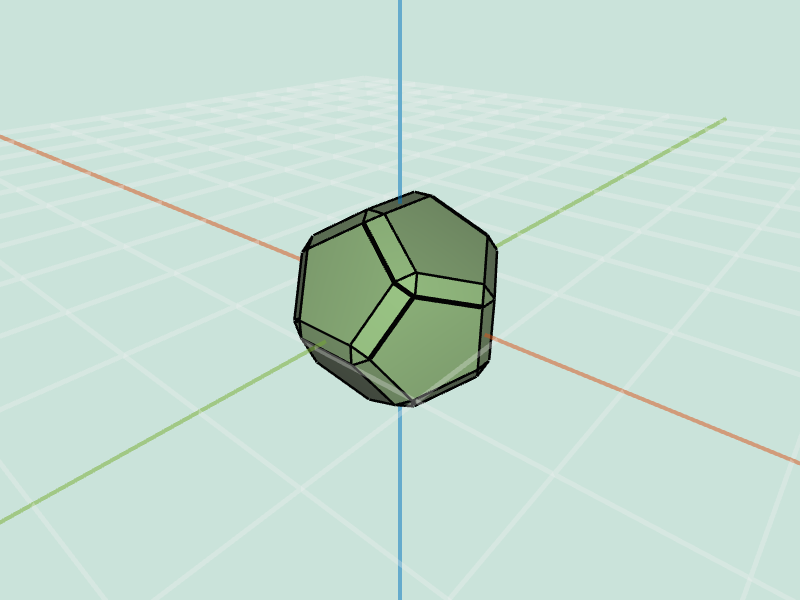 dodacahedron.obj bevel 0.2 |
tetrahedron.obj bevel 0.2 |
splitLong( mesh, factor )Depending on the choice of which vertices you selected to connect to a newly created one, you can obtain different results. Behavior you should be observing is splitting of the longest edge. Notice that as you go through iterations one of the newly added edges might be the longest one.
cube.obj splitLong 0.1 |
cube.obj splitLong 0.5 |
cube.obj splitLong 1.0 |
triSubdiv( mesh, levels )Splits each face into triangles. This effect is applied levels number of times. Mesh should be triangulated before using this function. In the example images input tetrahedron has been scaled (5) and rotated (1.57) for visualization purposes.
tetrahedron.obj triSubdiv 1 |
tetrahedron.obj triSubdiv 3 |
loop( mesh, levels )Splits each face into triangles. This effect is applied levels number of times. Mesh should be triangulated before using this function. In the example images input tetrahedron has been scaled (10) and rotated (1.57) for visualization purposes. In these examples we have used Warren weights.
tetrahedron.obj triSubdiv 1 |
tetrahedron.obj triSubdiv 3 |
cheetah.obj triSubdiv 1 |
cheetah.obj triSubdiv 3 |
tetrahedron.obj triSubdiv 1 |
tetrahedron.obj triSubdiv 3 |
cheetah.obj triSubdiv 1 |
cheetah.obj triSubdiv 3 |
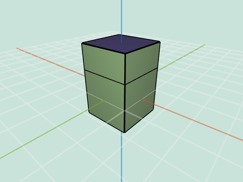
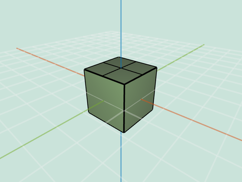
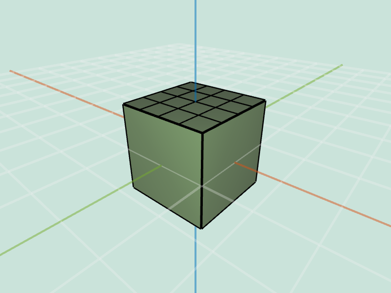
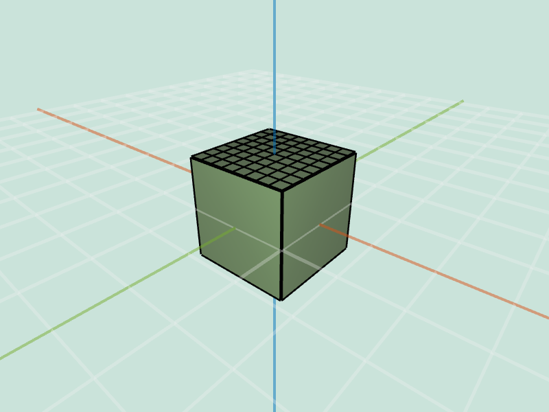
quadSubdiv( mesh, levels )Splits each face into quads. This effect is applied levels number of times.
 cube.obj quadSubdiv 1 |
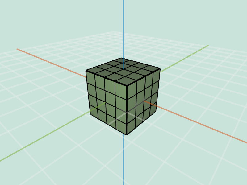 cube.obj quadSubdiv 2 |
 cube.obj quadSubdiv 3 |
 cube.obj (selected) quadSubdiv 1 |
 cube.obj (selected) quadSubdiv 2 |
 cube.obj (selected) quadSubdiv 3 |
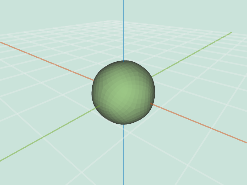
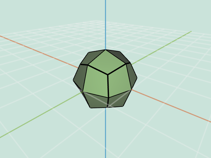
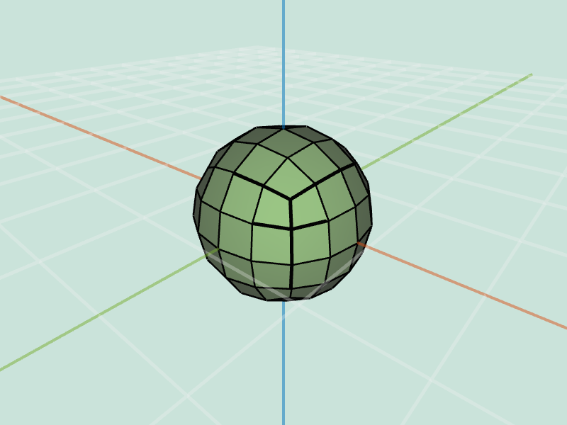
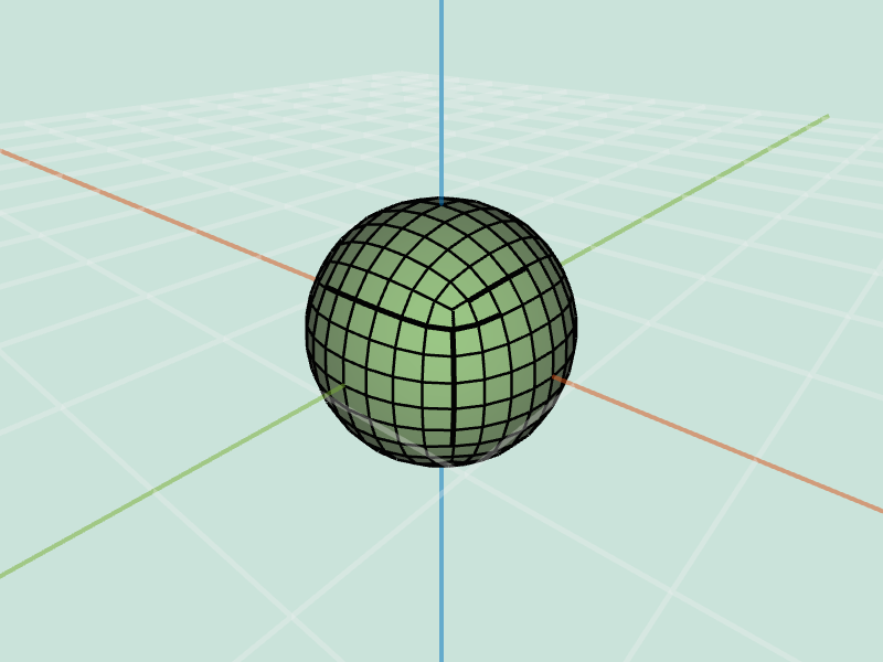
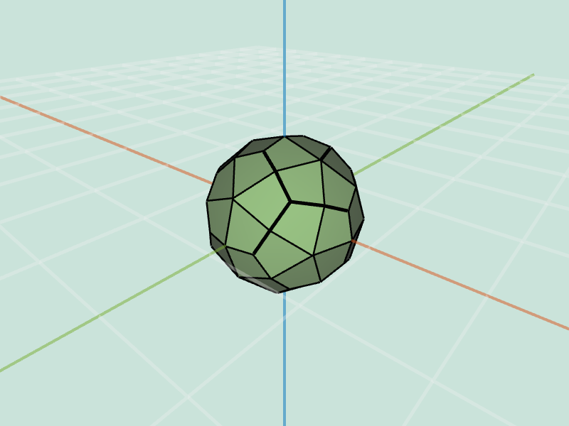
catmullClark( mesh, levels )Splits each face into quads. This effect is applied levels number of times. Uses update rules as given in slides. The order in which you should apply the geometrical changes is : modify positions of new edge midpoints, modify positions of newly created face centroids, modify positions of old vertices.
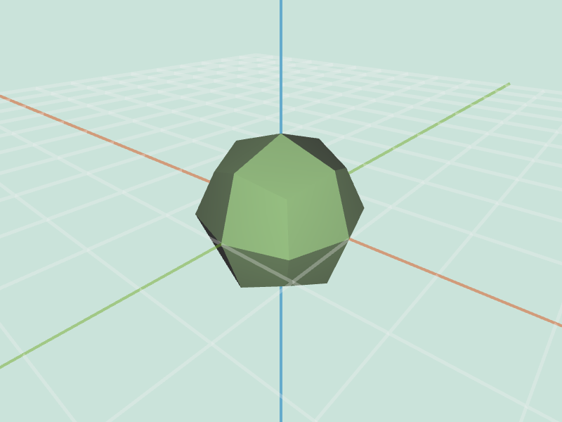 cube.obj catmullClark 1 |
 cube.obj catmullClark 2 |
 cube.obj catmullClark 3 |
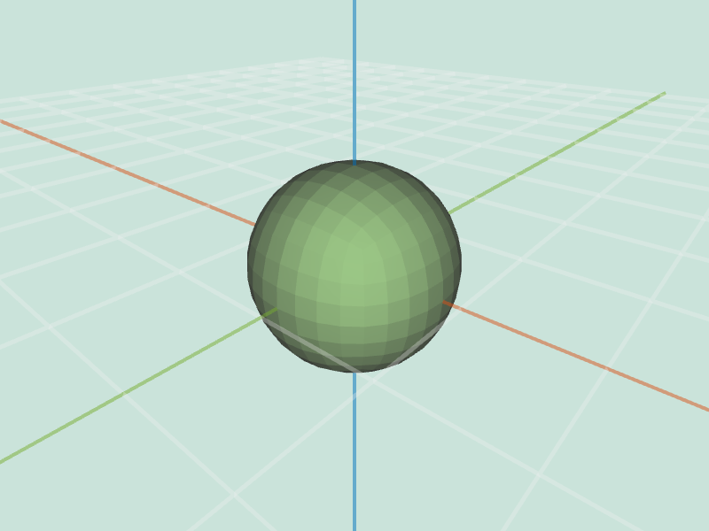
 dodacahedron.obj catmullClark 1 |
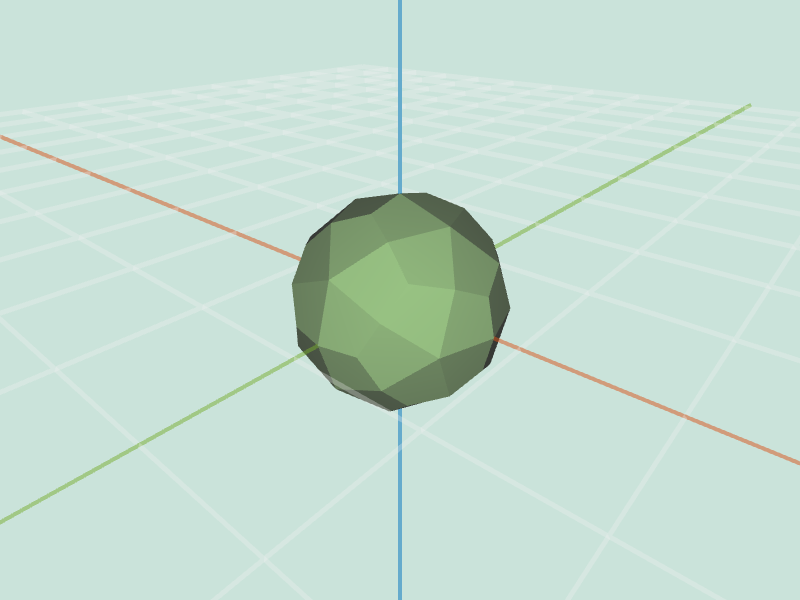
 dodacahedron.objquadSubdiv 2 |
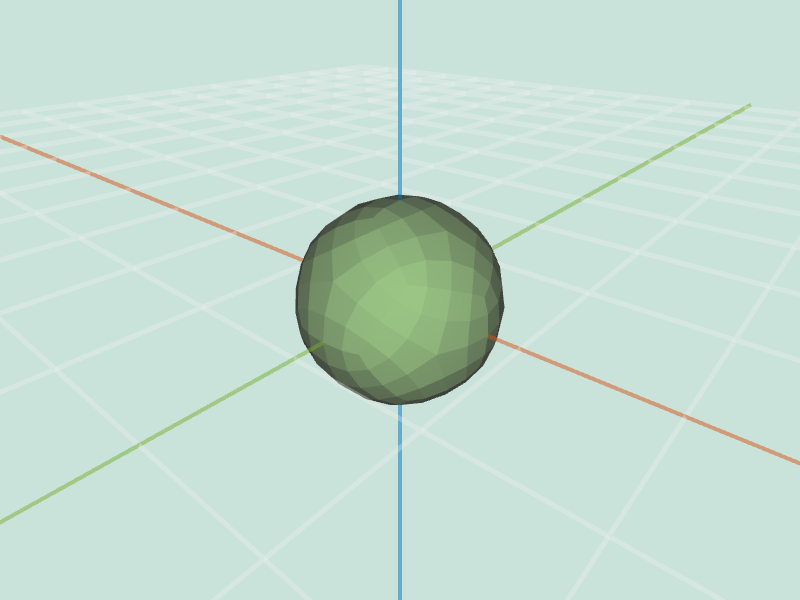
 dodacahedron.obj catmullClark 3 |
 cube.obj catmullClark 1 |
 cube.obj catmullClark 2 |
 cube.obj catmullClark 3 |
 dodacahedron.obj catmullClark 1 |
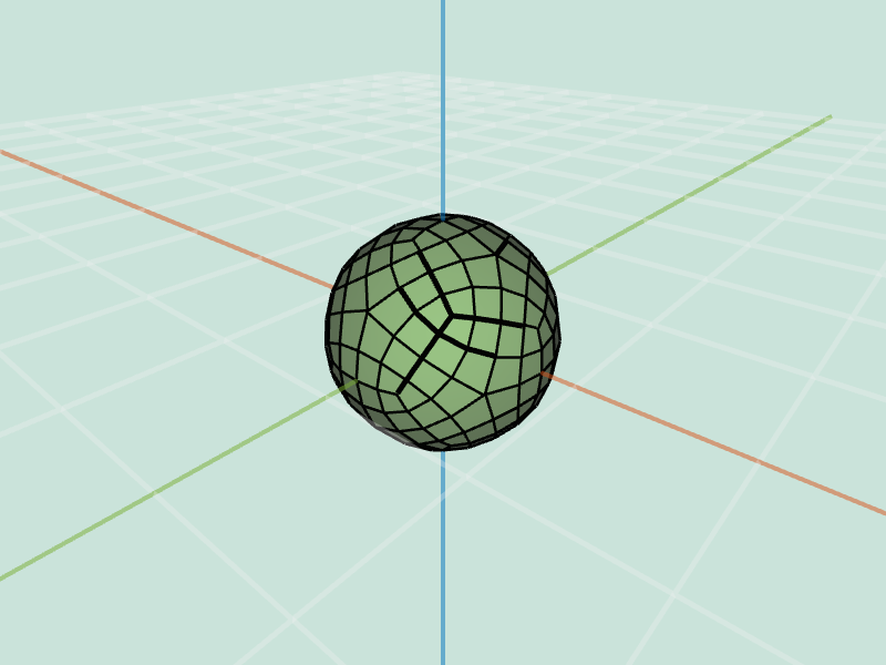 dodacahedron.obj catmullClark 2 |
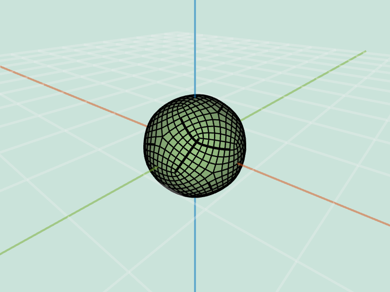 dodacahedron.obj catmullClark 3 |